EN
EN  English
 Español
 русский
 Deutsch
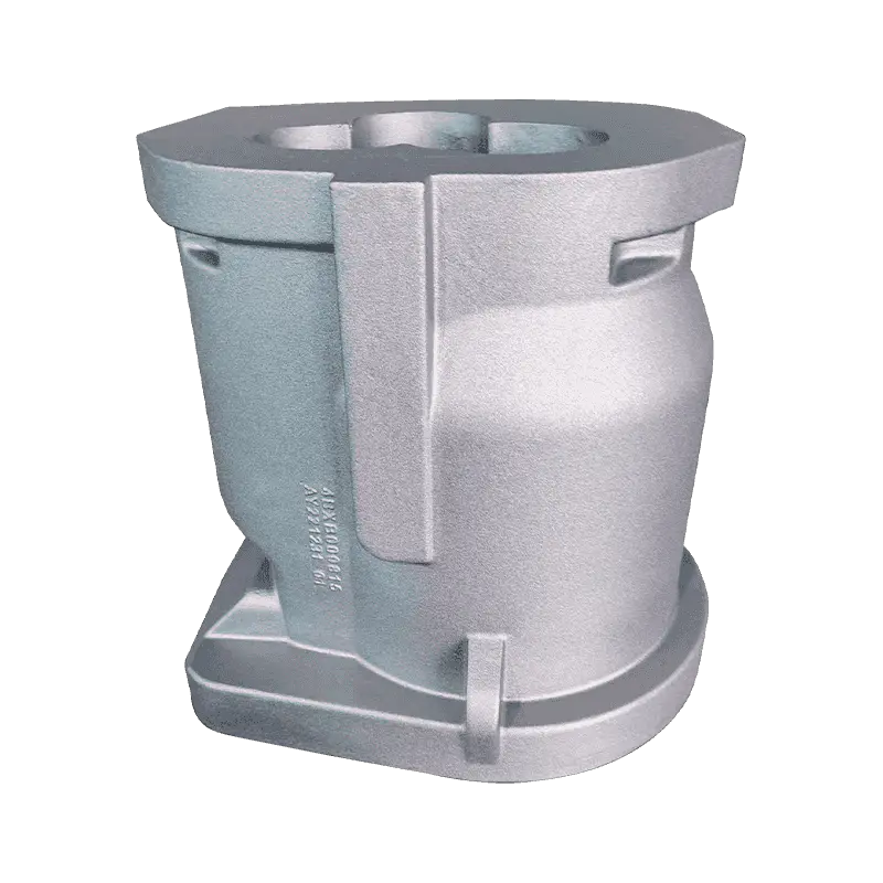
A 1.8-ton compressor body leaves the shakeout with clean edges and passes its dimensional check, then fails at the machining centre: a dark, smeared band opens up a few millimetres under the top face. The chemistry sheet looks reasonable and the casting is not porous. The defect is graphite flotation, and once it reaches a machined surface the heat, the melt treatment and the moulding cost are already spent.
The working rule is simple to state. Flotation is a density-driven defect of slow-cooling heavy sections, and it is controlled by matching carbon equivalent to section modulus, by cooling the top face on purpose, and by deciding in advance where the sacrificial metal will sit. Chemistry alone will not fix it, and a separately cast test bar will not warn you about it.
What Graphite Flotation Actually Is
Ductile iron solidifies through a eutectic reaction in which graphite grows as nodules inside the liquid. A nodule has a density of roughly 2.2 g/cm³; the surrounding liquid iron is close to 7 g/cm³. That gap is a buoyancy force, and in a casting that stays liquid for a long time it is enough to move nodules upwards through the melt.
In a 20 mm wall, freezing takes seconds and the nodules are locked where they form. In a 150 mm wall the same alloy can stay liquid for many minutes, and nodules that form early have time to rise. The result is a graphite-rich layer under the top face — often the top 5 to 30 mm, depending on section size and pouring temperature — sitting above a band whose structure and properties have quietly degraded.
Flotation is macrosegregation, not a nodularity problem. The affected band can show an acceptable nodule count under the microscope while tensile strength and elongation in that band have dropped sharply.
That distinction decides how the defect is inspected. A foundry can produce excellent nodularity, a clean matrix and a passing tensile test on a separately cast bar, and still ship a casting whose top face will not survive first machining. It also pays to separate flotation from the rest of the defect family: chunky graphite appears in heavy sections as a clustered, vermicular-like degeneration rather than a physical migration of nodules, and exploded graphite usually points to a melt-treatment problem. The remedies differ, so the diagnosis has to be specific.
Operators meeting the defect for the first time tend to blame pouring practice. It is worth going back to the material itself — a short refresher on what ductile iron delivers in service puts the problem in perspective before the melting shop takes the blame.
Carbon Equivalent and Section Modulus: The Two Numbers That Matter
Two variables decide most of the outcome. The first is carbon equivalent, CE = C + Si/3, with phosphorus added by some shops. The second is section modulus, the volume-to-surface ratio of the heaviest part of the casting, because it fixes how long the metal stays liquid after filling.
Published reviews of heavy-section ductile iron place the flotation risk above roughly 4.5% CE, and the risk climbs as section size grows. That is why carbon and silicon have to be correlated with section modulus instead of being chosen once and reused across a product family: a chemistry that pours beautifully into a thin pump cover will float in a thick compressor body.
| Variable | Why it moves flotation risk | Direction for heavy sections |
|---|---|---|
| Carbon equivalent | Sets total eutectic graphite and fluidity; a long solidification window lets nodules travel | Hold near 4.1 to 4.4%, at the lower end once wall thickness passes about 100 mm |
| Carbon | Carbon is the material that floats; every extra tenth adds volume to the accumulation band | Typically 3.5 to 3.7% rather than 3.8% and above |
| Silicon | Raises CE by roughly one third of its own weight and promotes graphitisation | 2.0 to 2.5%, chosen against the CE ceiling rather than against the grade alone |
| Pouring temperature | Extra superheat lengthens the time the casting stays liquid | As cool as the mould fills reliably, often 1,360 to 1,400 °C |
| Top-face cooling | Freezing the top early locks nodules in place | Chills, dense facing sand, no hot top left open |
| Riser position | A top riser holds a liquid pool exactly where nodules collect | Feed from the side or bottom where geometry allows; chill beneath the top face |
The table is a direction of travel, not a recipe. Two foundries working with the same section modulus can settle on different carbon levels and both be right, because sand properties, chill practice and pouring temperature differ. What should not differ is the discipline of writing a target CE against the section modulus before the pattern is mounted, and re-checking it whenever a customer thickens a wall or adds a boss.
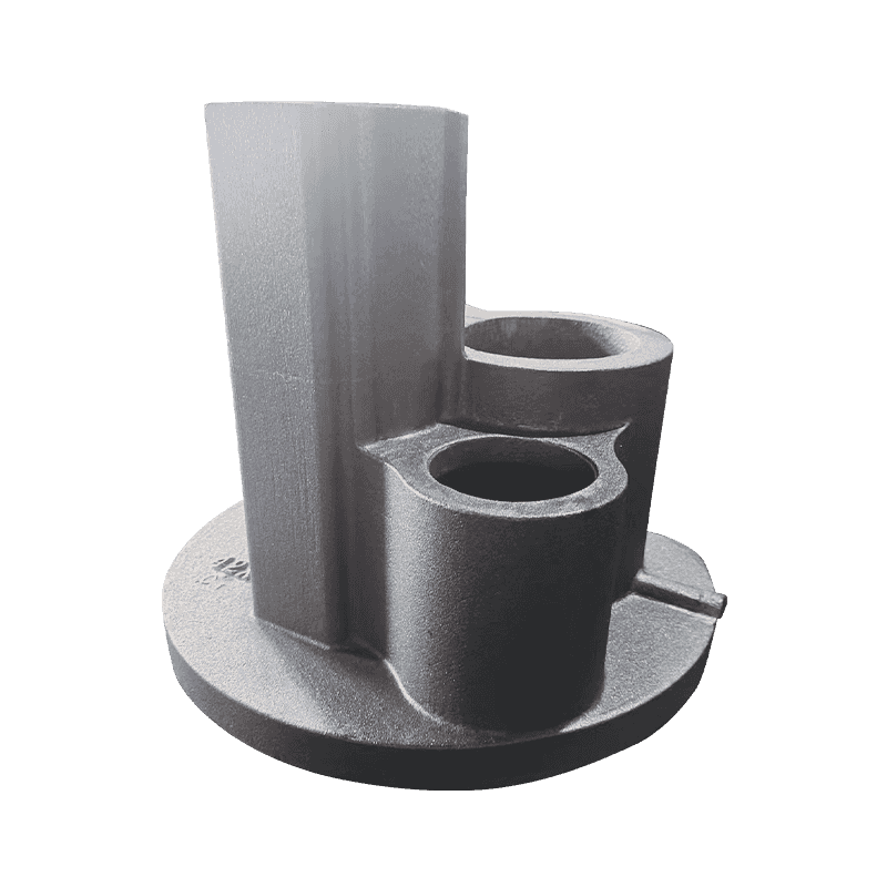
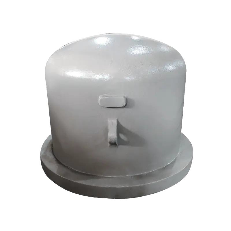
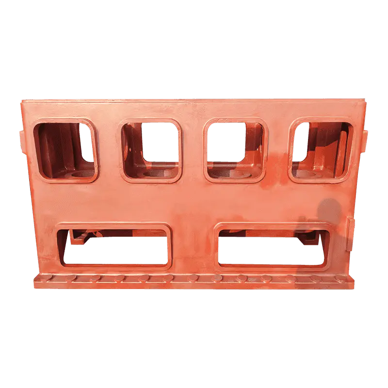
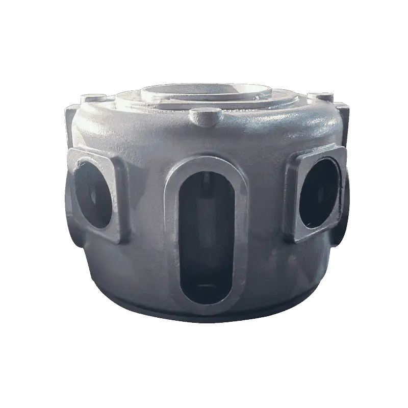
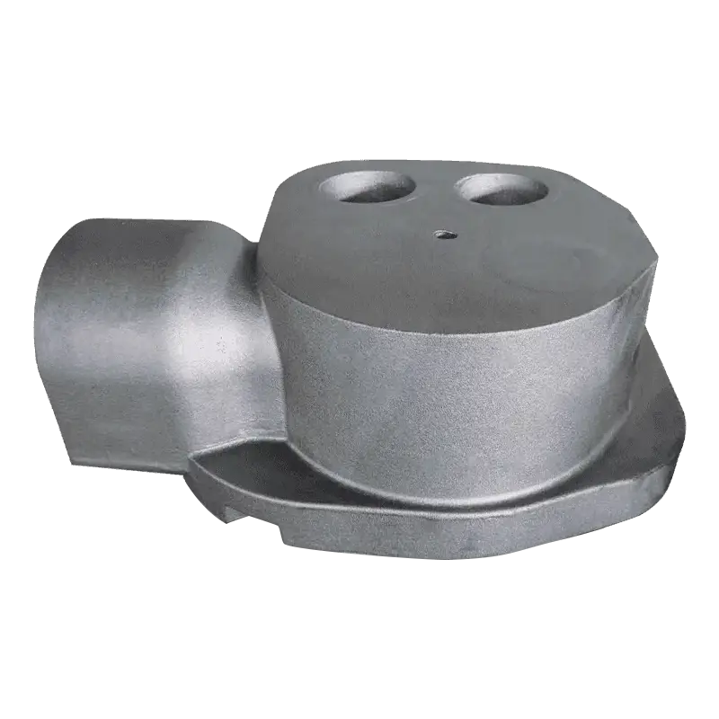
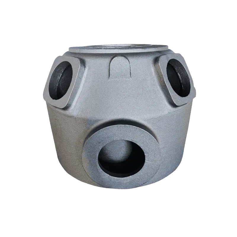
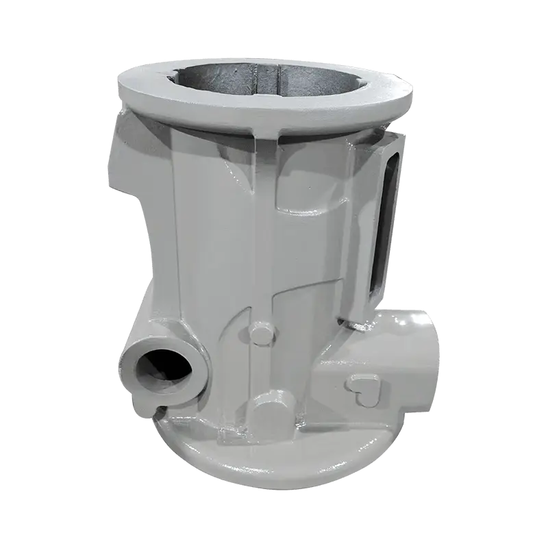
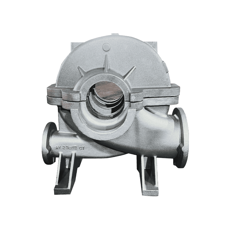
Thick-shell parts are where the arithmetic bites: a compressor body with a 60 to 90 mm wall, a machine base with a heavy central mass, or a pump housing with a deep flange all give nodules a long ride to the top.
Reading the Signs Before the Machining Line Does
Flotation rarely announces itself in the foundry. It appears at the machining centre, in rework, or in a customer complaint. The signals are consistent enough to build a routine around:
- Surface appearance: the top face can look slightly duller or rougher after blasting, and rough machining opens dark streaks that follow the surface rather than crossing it.
- In-situ metallography: a sample cut from the top face of a trial casting, or from a moulded-on lug with the same modulus, reveals an accumulation band that a separately cast bar never shows.
- Hardness mapping: the floated zone often reads softer and more ferritic than the bulk of the casting, which shows clearly on a mapped grid.
- Ultrasonic velocity and attenuation: useful for screening once readings are calibrated against sectioned samples of the same geometry.
- Destructive sectioning: still the reference method, and worth the cost on every new pattern or significant chemistry change.
Do not approve a heavy-section casting on the strength of a separately cast test bar alone. Bars are poured thin, they freeze fast, and they are immune to the defect you are trying to catch.
The cheapest early warning is a trial casting sectioned through the heaviest wall. One cut through the top face tells you more about carbon equivalent, chill placement and riser position than a month of tensile tests.
Countermeasures That Hold Up in Production
- Set the chemistry to the section, not to the grade. Pull carbon down first, then trim silicon against the CE ceiling; if a specification pushes silicon up for a matrix requirement, carbon has to come down further.
- Freeze the top face first. External or internal chills, or a facing sand that pulls heat faster, shorten the window in which nodules can travel. Size the chill against the actual hot spot rather than dotting it across the face.
- Pour as cool as the mould fills reliably. Superheat buys fluidity and costs flotation resistance; 1,360 to 1,400 °C covers most heavy-section work, and long holding in the furnace works against you too.
- Decide where the defect is allowed to live. Critical machined faces belong at the bottom or on a side of the mould; the top face gets a sacrificial allowance, 10 to 25 mm as a common starting point, machined away with the floated band inside it.
- Keep melt treatment tight. Magnesium residual around 0.03 to 0.05%, low rare earth content, prompt inoculation and no unnecessary re-heating all reduce the chance that a treatment problem compounds a flotation problem.
- Verify per heat, not per year. A sectioned sample from the first casting of a new pattern, plus periodic metallography from the top face, catches a drifting carbon equivalent before a batch reaches the machining line.
None of that is expensive on its own, and for a heavy one-piece structure — a machine base, a compressor body, a pump housing — the sectioned first article pays for itself the first time it prevents a scrapped casting.
What to Ask Before You Place the Order
If you buy heavy-section ductile iron castings, flotation is a supplier question as much as a foundry question. The answers you want are specific, and the questions are short:
- Which section modulus did you build the chemistry around, and what carbon equivalent did you target for it?
- Where do you take the metallographic sample, from the casting itself or from a separately cast bar?
- How do you control cooling on the top face, and what is the riser position?
- What machining allowance do you leave on the top face, and how did you arrive at that number?
- Do you record carbon, silicon, magnesium and pouring temperature for every heat, and can I see the last six months of that data?
A supplier who answers the first two questions in general terms and the last one with a promise is quoting on price rather than on structure. The commercial consequence deserves stating plainly: a casting that passes its certificate and fails at the machining centre is the most expensive kind of scrap, because the buyer has already paid for transport, machining time and a stopped production line.
The suppliers who handle heavy sections well usually answer these questions before they are asked; section modulus, target carbon equivalent, chill layout and sampling position tend to appear in the quotation package without prompting.
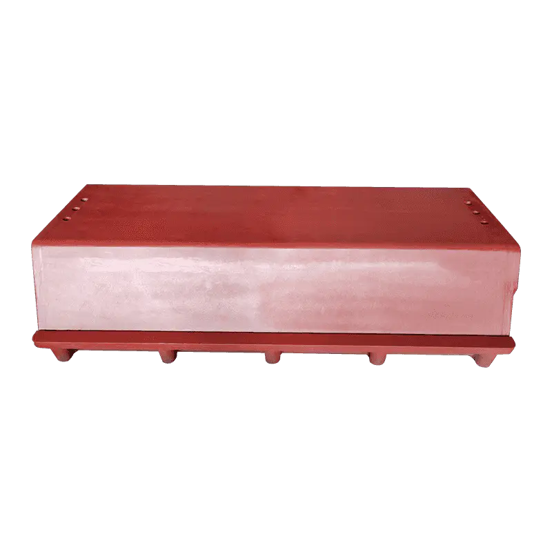
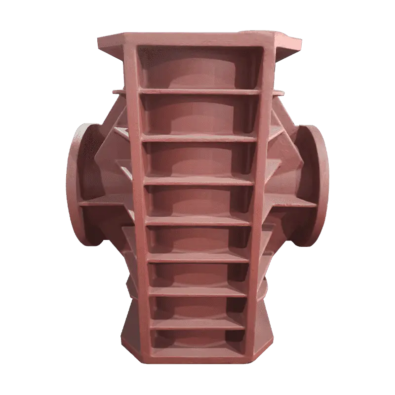
The same discipline runs through the ductile iron casting range built around compressor, pump, valve and machine tool components, where wall thickness varies enough that no single chemistry covers every part.
Graphite flotation is not a mysterious defect once the physics is on the table. Nodules are lighter than the liquid that carries them, heavy sections stay liquid long enough for that difference to matter, and the metal that ends up under the top face is not the metal the drawing assumes.
Control it with three decisions made early: carbon equivalent matched to section modulus, deliberate cooling of the top face, and a machining allowance that keeps the floated band inside the scrap bin rather than inside the finished part. Everything after that — test bars, certificates and inspection reports — is confirmation, not protection.