EN
EN  English
 Español
 русский
 Deutsch
Chunky Graphite in Ductile Iron Castings: Why It Forms and How Foundries Prevent It
A ductile iron machine base with walls approaching 200 mm leaves the foundry looking perfect — clean surfaces, sound dimensions, normal hardness. Months later, a sample machined from the center of the thickest wall tests at 3 to 4 percent elongation instead of the 10 percent the grade promises, or a fatigue crack opens beside a bearing seat. Section the casting at that spot and the graphite looks wrong: instead of discrete round nodules, the microscope shows clusters of connected, coral-shaped particles packed between dendrite arms. That is chunky graphite, and the material was compromised before the part ever carried a load.
The short version: chunky graphite is the characteristic defect of heavy-section ductile iron. It forms where solidification is slowest, thrives on high silicon, high carbon equivalent and residual rare earths, and damages elongation and fatigue strength far more than hardness ever reveals. Both preconditions — a slow-cooling hotspot and a permissive chemistry — can be engineered away, which makes it one of the most controllable defects a foundry faces. What follows covers the defect itself, the damage it does, and the countermeasures that hold up in production.
What Chunky Graphite Actually Is
Chunky graphite is not a foreign inclusion or a shrinkage cavity. It is a graphite morphology: carbon that should have frozen into isolated spherical nodules instead grows as aggregated, interconnected particles that look exploded or vermicular under the microscope. It appears in clusters or in interdendritic positions, and at a casual glance it can be mistaken for the type D graphite of thin-walled irons — although it belongs to heavy, slowly cooled sections, not to fast-freezing thin walls.
Two habits make it easy to miss. First, it concentrates in the thermal center of a heavy section — the last metal to solidify — while graphite form at the skin and in routine coupons can look perfectly normal. Second, on a machined or fractured surface it shows itself only as a localized darkening, a fuzzy gray patch that is easy to misread as staining or a feeding problem. By the time it is obvious in a fracture, the connected graphite has already built a network of ready-made crack paths.
If you need a refresher first, our plain-language introduction to ductile iron covers how the material differs from gray iron.
Why Heavy Sections and Slow Cooling Trigger It
The controlling variable is local solidification time. In a 25 mm wall the eutectic reaction finishes quickly and every nodule grows independently into a sphere. In the core of a machine column or a compressor crankcase hub, the same reaction can stretch out many times longer — and the graphite particles suspended in the last liquid between eutectic cells then connect and grow as an aggregate instead of staying separate. The defect appears exactly where experience predicts: at wall junctions, in thick bosses, under feeder sand.
Chemistry decides whether that slow cooling is allowed to do damage. Three composition factors come up consistently. Silicon is the dominant one: the defect is rare near 2 percent silicon and its incidence climbs steeply toward and beyond 3 percent, which is one reason high-silicon solution-strengthened ferritic grades demand extra care in heavy sections. A high carbon equivalent adds exposure. Rare earths are subtler — cerium and lanthanum are needed in small amounts for a robust nodularizing reaction, yet intermediate residuals are repeatedly linked to chunky graphite in heavy plates and bars.
Chunky graphite is not bad luck. It is what ductile iron does when slow cooling meets a permissive chemistry — and both variables can be managed.
The Damage It Does to Mechanical Properties
The losses are not uniform, and that asymmetry is what makes the defect dangerous. Hardness barely moves, because the metal matrix is largely unchanged. Tensile strength in an affected zone typically drops by roughly 10 to 20 percent. Elongation is hit far harder — losses of half or more are commonly reported once chunky graphite occupies a significant share of the fracture surface. Fatigue strength usually suffers most of all, because interconnected graphite acts as an internal notch: a crack no longer needs to start at the surface, it can begin deep inside the wall.
Danger — Hardness will not catch this defect. A chunky-affected region can measure completely normal on a hardness test while its elongation and fatigue life have quietly collapsed. Heavy-section acceptance must rest on tensile testing of representative material.
| Property | Typical effect | Why |
|---|---|---|
| Tensile strength | Reduced by roughly 10-20 percent | Connected graphite replaces load-bearing matrix with weak internal interfaces |
| Elongation | Frequently cut by half or more | The graphite network offers a continuous, low-resistance crack path |
| Fatigue strength | Reduced most severely in practice | Internal graphite clusters act as subsurface crack initiators |
| Hardness | Little or no measurable change | The metal matrix is essentially unaffected |
How Foundries Find It Before the Customer Does
Detection has to go looking for the defect, because the defect does not come to routine inspection. The direct method is sectioning: cut the casting — or a sacrificial sample from the same thermal position — at the known hotspots, prepare the surface, and evaluate graphite form metallographically against standard comparison charts. Inspectors also watch for the localized darkening described above on machined or fractured surfaces. For castings too large to section, ultrasonic testing serves as a screening tool, since degraded graphite forms measurably lower sound velocity; any flagged area is then confirmed metallographically.
Info — A separately cast test bar describes the melt, not the casting. For heavy sections, insist on coupons attached to the thickest walls, or samples cut from defined hotspot zones, before accepting any property result.
Prevention: Chemistry and Solidification, Managed Together
Chemistry levers
The first lever is composition. Foundries that pour heavy sections routinely hold silicon as low as the grade allows — for structural ferritic ductile irons that usually means staying in the 2.0 to 2.4 percent range rather than drifting toward 3 — and keep carbon equivalent under control for the same reason. Residual rare earths are managed deliberately: enough to guarantee nodularity, never more than necessary. Where a section needs extra insurance, micro-additions of antimony on the order of tens of ppm are an established countermeasure, and in high-silicon grades tin has shown a similar suppressive effect.
Warning — These additions work precisely because they are small. Excess antimony promotes degenerate graphite forms of its own, and stripping rare earths entirely leaves the nodularizing reaction fragile against trace harmful elements. The countermeasures function as a balanced window, not as independent switches.
Cooling and design levers
The second lever is solidification itself. Chills against hotspot walls, ribs and fins that thin out massive junctions, and honestly proportioned wall sections all shorten local solidification time — the root cause of the defect. Feeding design matters too, because a hotspot that is fed but not chilled still spends too long above the solidus. Solidification simulation, run before the first casting is poured, locates the thermal centers on the computer instead of in the scrap bin.
| Lever | Practical action | Trade-off to watch |
|---|---|---|
| Silicon window | Hold silicon near the low end of the grade, about 2.0-2.4 percent for structural grades | Very low silicon costs some strength and shifts shrinkage behavior |
| Rare earth residuals | Cap residuals at the level needed for robust nodularity | Too little weakens the nodularizing reaction |
| Antimony or tin | Small deliberate additions in the tens of ppm | Overdosing causes other degenerate graphite forms |
| Local cooling | Chills, ribs, fins and thinner junctions at hotspots | Added cost; must not create cold shuts or feeding problems |
What Buyers Should Put in the Specification
Much of the protection a buyer receives is decided at the specification stage. Name the grade unambiguously — ASTM A536 65-45-12 or 80-55-06, or the EN-GJS and ISO 1083 equivalents — then state where the properties must be proven. A requirement that tensile coupons be attached to the heaviest walls, or cut from defined zones, changes foundry behavior in a way a number on a drawing never will. Define graphite acceptance on hotspot sections with reference to standard comparison charts, and for genuinely massive parts consider contractual ultrasonic screening.
Heat treatment state deserves its own line as well. A ferritizing anneal gives the elongation-rich grades their character, but no anneal can repair chunky graphite that formed during solidification.
A grade number on a drawing proves nothing about the center of a 200 mm wall. The sampling location does.
Success — The most valuable sentence in a heavy-section casting specification is the one that names the sampling location. Everything else follows from it.
Where the Risk Concentrates in Real Components
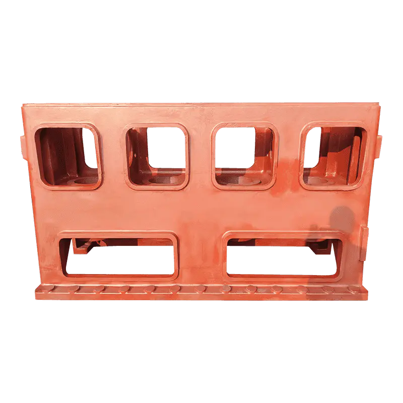
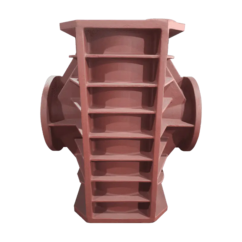
The most exposed components are the ones end users rarely see: massive, load-bearing ductile iron shapes with thick, intersecting walls. Machine tool bases concentrate metal in exactly the way that produces long solidification times, and their dimensional stability across years of service depends on a sound matrix inside the wall. We treat them as a chunky-graphite watch item from the first simulation onward.
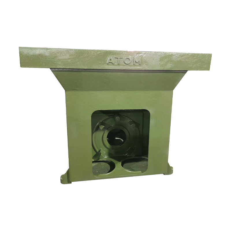 Ductile Iron Machine Tool Base CastingThis resin sand cast base supports spindles, beds and worktables, providing the stiffness and vibration resistance that keep machine tools accurate. Its thick intersecting walls demand sound graphite form inside the casting.View Product →
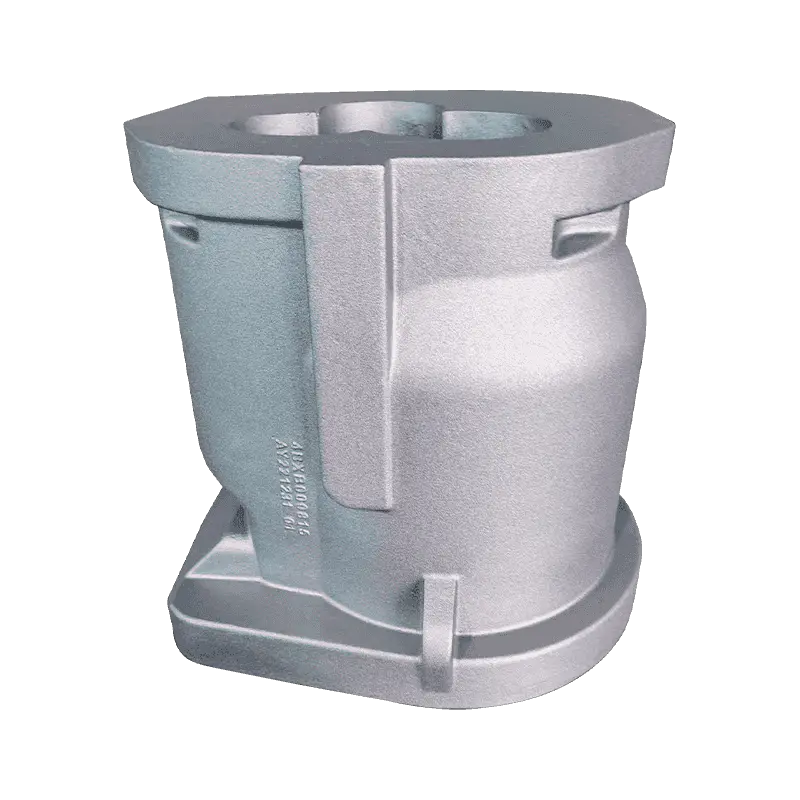
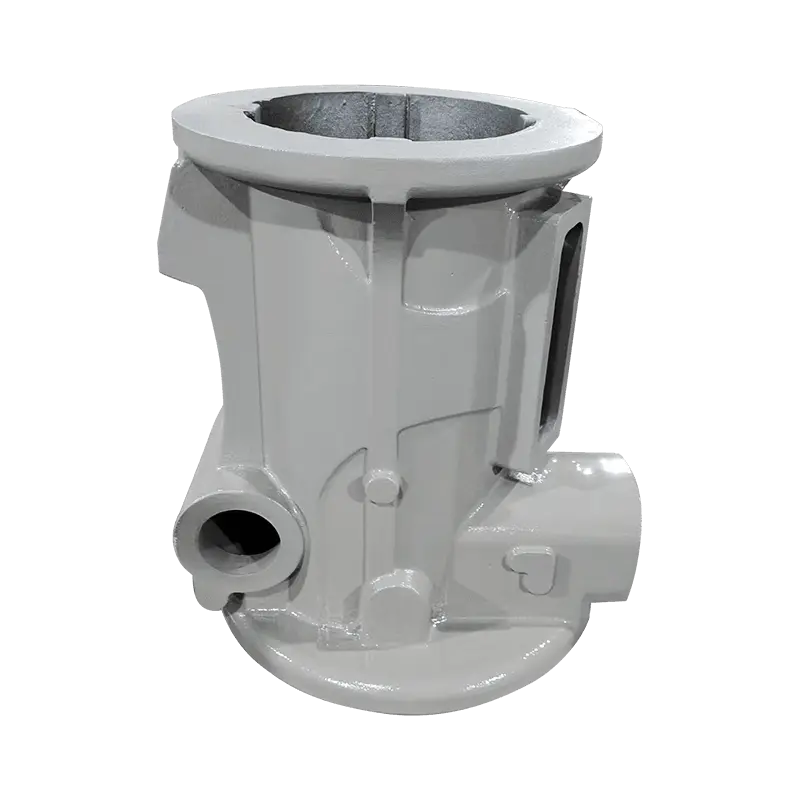
Machine tool columns carry the same profile — tall, thick and structurally central — with the added demand that geometry stay true while the machine is cutting. Graphite form inside the wall is part of that promise.
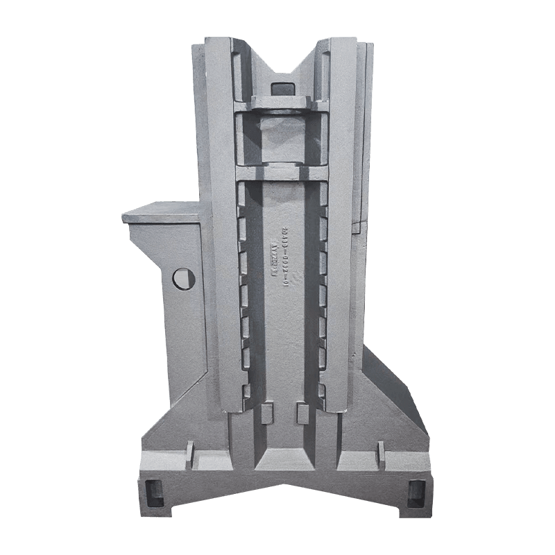 Machine Tool Column Casting for Rigidity and PositioningThe column supports and positions tool, worktable or workpiece, and must hold geometry true while cutting. Tall, thick-walled sections make internal graphite structure and dimensional stability the key quality concerns here.View Product →
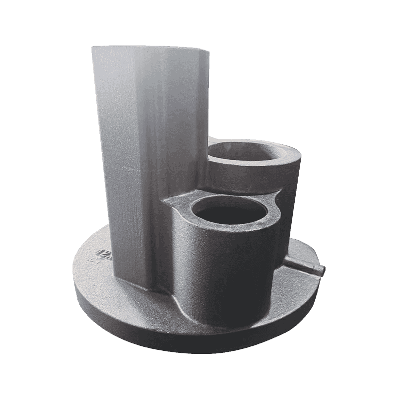
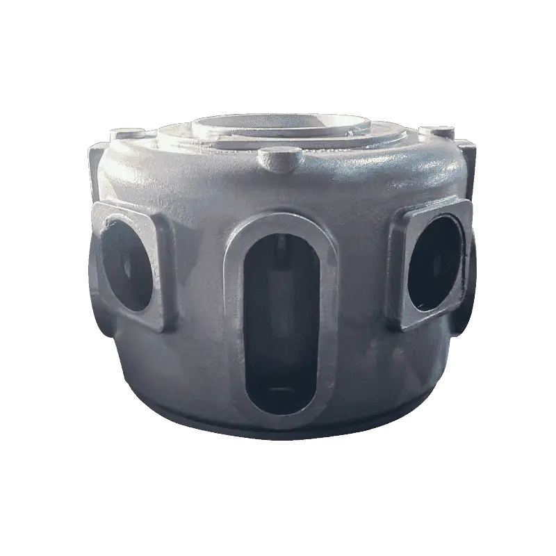
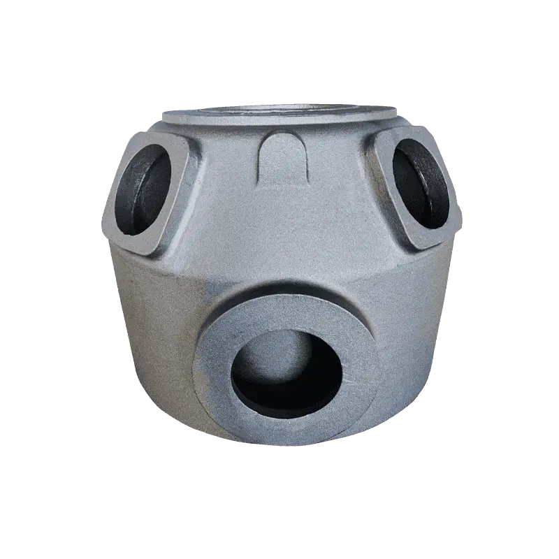
Compressor components combine section thickness with rotating duty. Crankcases and bodies stack thick bearing-seat bosses and cylinder walls into a single casting, and rotating equipment is unforgiving toward internal defects. Our compressor casting program covers bodies, crankcases, bearing seats, rotor seats and cylinders where this combination is routine.
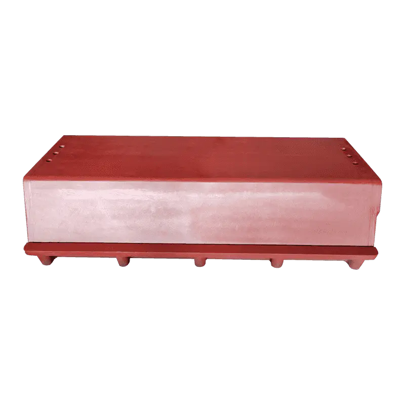 Compressor Crankcase Casting with Thick Bearing SeatsThis crankcase combines heavy sections, bearing-seat bosses and cylinder walls in one casting for rotating duty. Rotating equipment tolerates few internal defects, so sound solidification in thick walls is essential.View Product →
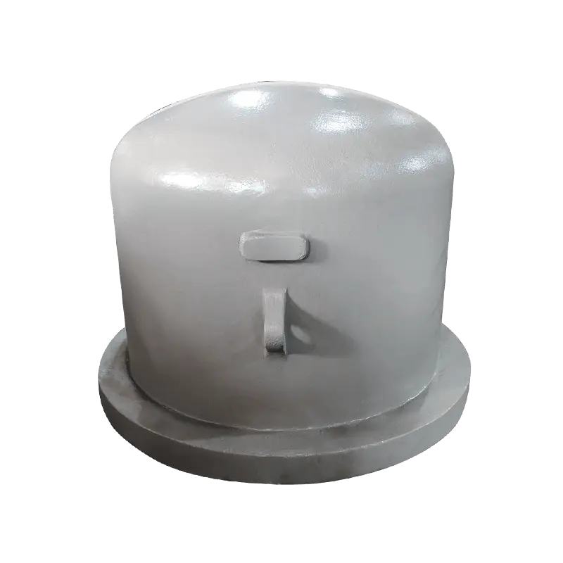
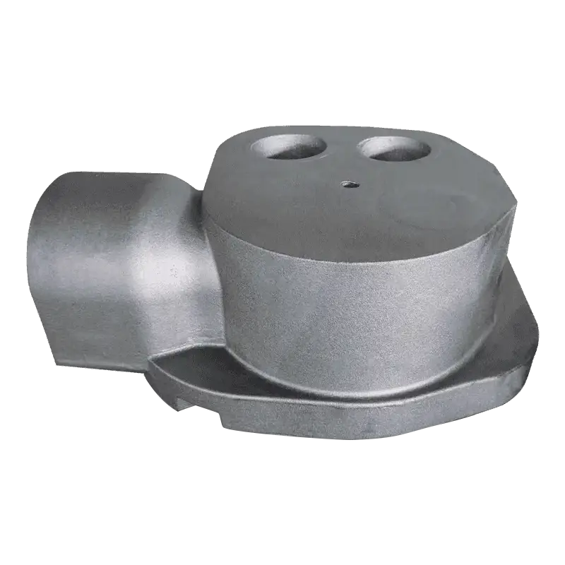
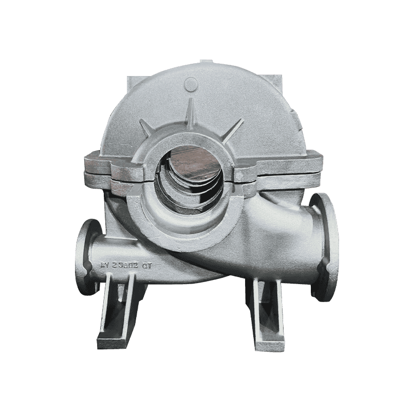
Pump bodies and pressure-retaining parts add cyclic loading on top of heavy sections, and wind energy components — hubs and main frames in heavy-section ductile iron — sit at the most demanding end of the same problem.
The Bottom Line
Chunky graphite in ductile iron castings is a defect of time and chemistry: it grows where heavy sections cool slowly and a permissive composition lets it, it leaves hardness untouched, and it takes elongation and fatigue strength down disproportionately while hiding from routine checks.
- It forms in the thermal centers of heavy sections, not in thin walls.
- Silicon drifting toward 3 percent, high carbon equivalent and intermediate rare earth residuals raise the risk.
- Detection means sectioning hotspots for metallography — hardness and skin samples will not reveal it.
- Low-end silicon windows, capped rare earth residuals, small antimony or tin additions and local cooling all suppress it.
- The buyer's strongest tool is a specification that names the grade, the sampling location and hotspot-based graphite acceptance.
None of these measures is exotic; they are standard practice in any foundry that regularly pours multi-tonne bases and frames. The difference between a heavy casting that runs for decades and one that cracks in service is usually decided months before delivery — in the chemistry sheet, the simulation model and the sampling plan. Foundries that control those documents, and buyers who read them, rarely meet chunky graphite in a failure report.