EN
EN  English
 Español
 русский
 Deutsch
The Hard Truth About Carbides in Ductile Iron Castings
Four holes into a production run, the drill starts smoking. The material certificate says ductile iron, grade 80-55-06. A hardness spot check near a cored passage reads 312 HBW, far above spec. The chips are short, gritty, and gray instead of clean curls. The part is dimensionally compliant, but it will be difficult to machine and risky under load. The cause is almost certainly carbides.
Carbides in ductile iron castings rarely appear in incoming inspection. They hide behind an acceptable average hardness and a clean surface. They become visible when tools wear out in minutes, threads tear, or a pressure test fails. Understanding what creates them and how foundries keep them out is the most direct way to avoid paying for the same problem twice: once in the casting, once in machining and warranty.
The practical difference between a reliable ductile iron casting and a troublesome one is usually not the average hardness. It is the absence of hard, brittle phases in exactly the zones that must be machined and loaded.
What Carbides Are and Why They Appear
In a correctly solidified ductile iron structure, carbon precipitates as spheroidal graphite during eutectic solidification. Those graphite nodules give the iron its ductility, damping capacity, and machinability. The transformation depends on time and nucleation conditions.
When the local cooling rate is too fast, or when the melt composition drifts away from the graphite-stable zone, carbon combines directly with iron to form cementite (Fe3C). If cementite forms a connected network, the structure is called ledeburitic carbide. It is the same phase that gives white iron its hardness, but in ductile iron it is a defect, not a design feature.
Solidification research on nodular iron points to the same triggers:
- Fast cooling in thin sections. Cylinder walls, pump ribs, and guide edges solidify faster than heavy bosses, leaving little time for graphite to grow.
- Low carbon equivalent. A CE value below about 4.3 pushes solidification toward carbide formation.
- Carbide-stabilizing elements. Chromium, manganese, molybdenum, vanadium, and boron promote cementite even at moderate levels, often entering through unmonitored steel scrap.
- Inoculation fading. Inoculation provides the nucleation sites graphite needs. Too little inoculant, or too long a delay before pouring, leaves the melt without those sites.
- Localized thermal conditions. The last-freezing zones of a casting are where massive carbides concentrate.
"Carbides are the casting's memory of its own cooling history. The question is whether you read that memory before machining or after a failure."
Info. Carbides are not automatically a rejection cause. Some industrial specifications tolerate up to 3 percent carbide by area in defined non-functional zones. The issue is whether the tolerance is documented and agreed, or discovered by accident.
What Carbides Do to Machining and Service Life
The first rule of carbide problems: they are local. A single cold spot in one mold cavity can produce a carbide zone while the rest of the casting is sound. Average tensile samples can pass, and the casting can still destroy a cutter or crack in service.
Machining is usually where the problem appears first. Cementite is much harder than the pearlitic or ferritic matrix, so a cutting tool crossing a carbide zone experiences hard impacts. Tool life drops, dimensional control becomes unstable, and finish tears. In drilling, the difference between a good batch and a bad one is visible within the first few holes.
On the performance side, carbides remove the material's ability to deform plastically. A casting with a pronounced carbide network behaves like white iron: harder, but brittle. Elongation can fall below 3 percent, impact energy drops sharply, and the part becomes sensitive to notches and stress concentrations. That matters for pump bodies under pressure, compressor housings under thermal cycling, and machine tool structures that must hold alignment.
| Property | Normal ductile iron | With carbide network |
|---|---|---|
| Hardness (HBW) | 170 - 250 | 300 - 500 localized |
| Elongation (%) | 6 - 18 | Below 3 |
| Impact toughness (J) | 8 - 25 | Below 5 |
| Machinability | Good with standard tooling | Poor; rapid wear and chipping |
| Failure behavior | Ductile deformation with visible warning | Brittle fracture without significant warning |
Danger. In a pressure-containing part, a carbide zone at an internal corner acts as a crack starter. When pressure is applied, the hard zone cannot accommodate strain, and failure changes from leak-before-break to sudden fracture.
Process Controls That Keep Carbides Out
Carbide control depends on four variables: chemistry, inoculation, cooling rate, and heat treatment. The strongest foundries manage all four as one system, not as separate checkpoints.
Chemistry and carbon equivalent
For general engineering ductile iron, carbon equivalent is typically held between 4.3 and 4.6 percent, with silicon between 2.2 and 2.8 percent. The lower limit is critical: below the eutectic CE, the melt becomes more prone to carbide precipitation regardless of inoculation quality.
Late and reliable inoculation
Inoculation adds nucleation sites for graphite. Late inoculation, done in the pouring stream or at ladle transfer, gives the highest nuclei count when the metal enters the mold. The interval between inoculation and pouring matters as much as the inoculant amount; faded inoculation is a leading cause of batch-to-batch inconsistency.
Cooling rate and section design
The casting designer and the foundry should review thin sections, sharp transitions, and cored passages before the pattern is cut. Thin-wall compressor components are a classic example: cooling channels, narrow walls, and threaded zones create multiple locations with a high local cooling rate. Foundries that regularly produce such parts adapt gating, pouring temperature, and mold conditions to stay in the graphite-stable range.
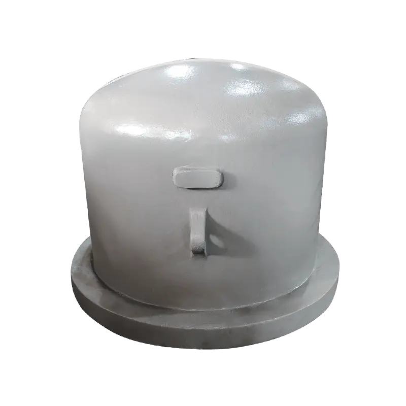
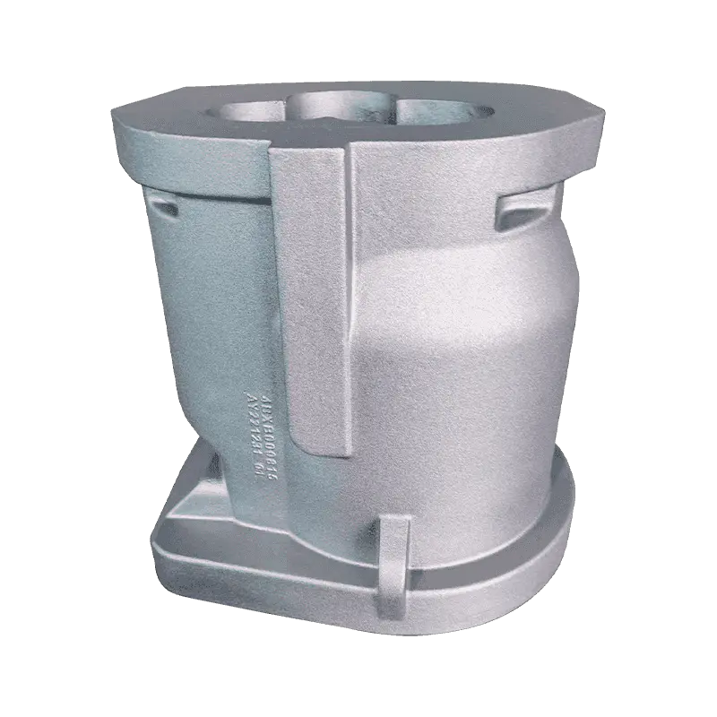
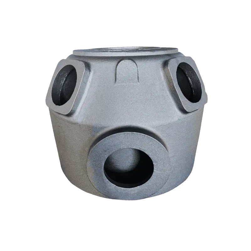 HT250 Compressor Cylinder with Resin Sand CastingThis pressure-bearing cylinder relies on high-strength HT250 cast iron and resin sand molding. Its thin walls and cooling channels create carbide-prone zones, making the transition-area risks discussed here directly relevant.View Product →
When a thin section adjoins a heavy one, solidification time changes abruptly, and that transition zone is where carbides prefer to appear. Pattern reviews, transition radii, and controlled mold cooling avoid the problem instead of correcting it later.
Heat treatment as a corrective step
If carbides have already formed, ferritizing annealing dissolves them. Holding the castings at about 900 degrees Celsius for one to three hours, then cooling slowly, allows cementite to decompose and carbon to precipitate as graphite. Heat treatment of machine tool castings follows the same logic: bring the matrix to the specified hardness and remove unstable phases. Heat treatment costs time and energy, so foundries treat it as a corrective step, not a substitute for process control.
Machine tool castings, with their heavy sections and long cooling times, are less exposed to thin-wall carbides but still need a defined annealing cycle to deliver a stable, uniform structure.
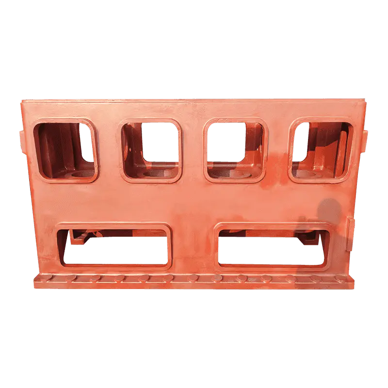
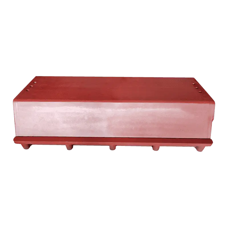
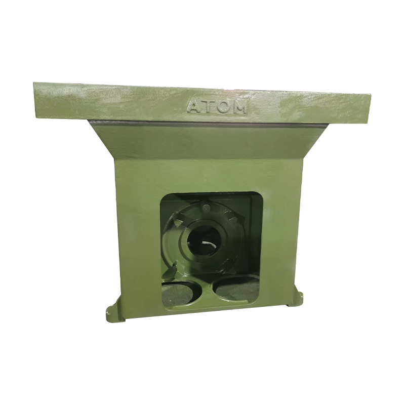 Stable Machine Base for Machine Tool SupportServing as the structural foundation of a machine tool, this base provides stiffness and vibration resistance. The surrounding text stresses that heavy-section castings still need a defined annealing cycle for consistent, uniform structure.View Product →
Success. A foundry that runs tight chemistry limits, late inoculation, and a defined annealing cycle can produce ductile iron that machines identically from batch to batch. That consistency is worth more than the savings from a cheaper charge mix.
What to Verify Before You Place the Order
Carbides are a process outcome, not a random event. A few targeted questions separate a foundry that controls its process from one hoping for the best. These checks take little time and prevent the surprise of carbide problems after machining starts.
- Review the full chemistry certificate. Most certificates list carbon and silicon. Ask additionally for chromium, manganese, molybdenum, and vanadium limits. A supplier not reporting these may not be monitoring them.
- Ask how inoculation is applied. Stream or ladle inoculation at the latest stage is a strong signal that nucleation is taken seriously.
- Define the matrix and heat treatment. State whether castings are delivered as-cast, normalized, or annealed, and which microstructure is expected in critical zones.
- Request a hardness map on the first article. Check hardness at thin sections and near machined bores, not only on the separately cast test bar. The gap between test-bar hardness and local hardness is where carbides hide.
- Write down carbide acceptance per zone. If the drawing cannot tolerate carbides in a specific area, say so. If small amounts are acceptable elsewhere, say that too.
Pump and valve castings are a typical case where this conversation pays off. A pump body must be pressure-tight, machined on several faces, and reliable under variable temperature. The carbide discussion moves quickly from "are any allowed" to "where exactly are they allowed."
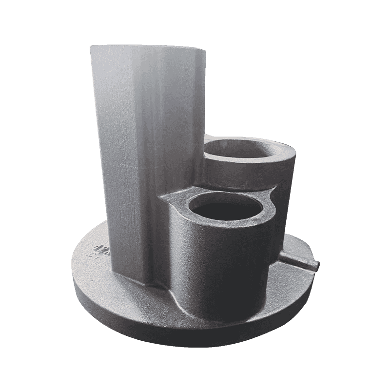
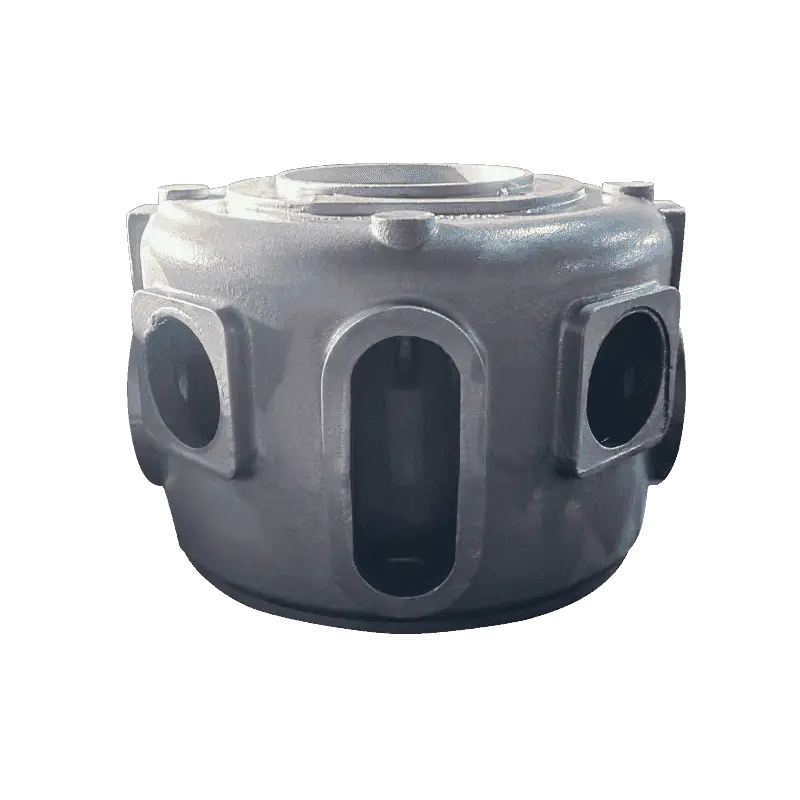
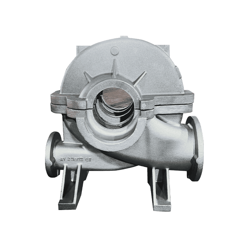
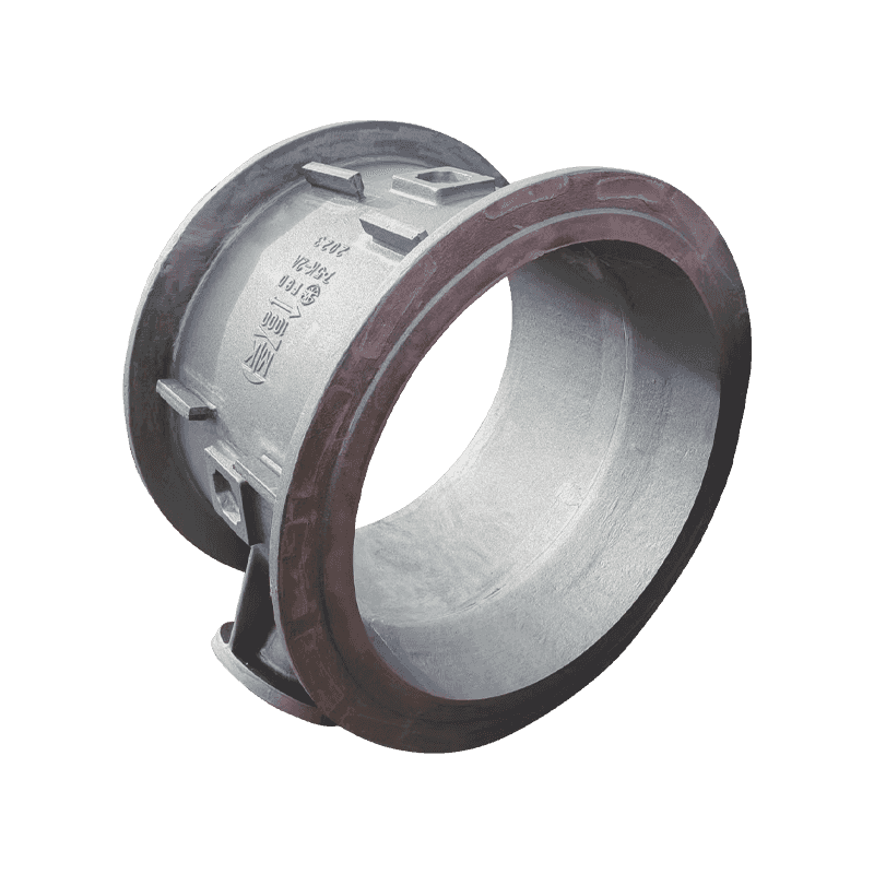 Pump Body Casting with Pressure-Tight ConstructionThis pump and valve body guides fluid flow and supports the valve with integrated channels. Its multiple machined faces and pressure-tight requirements align with the carbide-location discussion, making it a key item to review.View Product →
Before requesting quotes, review the supplier's existing portfolio. A foundry that already produces similar geometry has a measurable advantage; you can inspect the product range and judge whether the castings in production match the parts you need.
Warning. A quote noticeably lower than the market average deserves extra questions, not fewer. The difference between a controlled charge and a cheap charge is often visible in the amount of carbide-stabilizing elements entering the melt.
The Takeaway: Carbides Can Be Managed, But Only if You Ask
Carbide formation in ductile iron castings is predictable. It follows from local cooling rate, composition, and nucleation conditions, and it can be controlled through deliberate process design. The cost of prevention is modest: disciplined chemistry limits, timely inoculation, and a heat treatment step where needed. The cost of discovering carbides late is high: scrapped machining, failed pressure tests, machine downtime, and disputed deliveries.
The best time to deal with carbides is before the pattern is cut and the purchase order is signed. The second best time is now, while you still control the specification, the verification plan, and the conversation with your supplier.