EN
 English
 Español
 русский
 Deutsch

Machining Ductile Iron Castings: What Sets the Cost per Part
Nodular graphite makes ductile iron strong, tough and worth specifying. It also makes the chips stringy, the heat stubborn and the tolerance window narrower than most drawings admit. Grade control and fixturing decide more than any insert catalogue.
Two bearing housings, cast in the same week from the same pattern, can behave like two different materials on one machine. One bores cleanly at 220 m/min. The other dulls an insert corner before the tool reaches full depth. The program never changed. The castings did: a pearlite-heavy section near a riser, a chill skin on a thin rib, or a 40 HBW swing across the batch.
Metallurgy sets the ceiling, fixturing sets the floor, and cutting data only works inside the window between them.
Why Ductile Iron Machines Differently from Gray Iron
In gray iron, graphite forms flakes that sit inside the matrix like thousands of small internal chip breakers. Chips shear short and the cut feels light. Magnesium treatment turns that graphite into nodules, which is what gives ductile iron its strength and elongation, and also what removes the built-in chip breaking.
On the machine the result is predictable: longer, stringier chips, higher cutting forces at the same depth of cut, and more heat held in the cutting edge because the chip carries less of it away. The matrix around those nodules then decides how the tool wears.
- Ferritic, around 170-210 HBW. Soft and gummy; built-up edge, smeared finishes and drifting dimensions at low speed.
- Pearlitic, around 230-290 HBW. Abrasive; flank wear and notch wear take over, and tool life drops quickly as hardness climbs.
- Mixed as-cast structure. One grade can read 200 HBW in a thin flange and 250 HBW in a heavy boss, purely because the cooling rate differs.
- Nodularity and nodule count. Fine, high-count graphite machines consistently; coarse or degenerate graphite becomes a machining problem long before it becomes a strength problem.
Two castings can carry the same grade stamp and still differ by 40 HBW. That difference never appears on the drawing. It appears on the insert invoice.
One detail worth repeating: ductile iron fines are not harmless. Dry roughing produces a fine graphite-rich dust, so extraction at the cut belongs to the process, not to the housekeeping.
Cutting Parameters That Hold Up on the Shop Floor
The figures below are starting points for coated carbide on a rigid machine, not promises. Ductile iron cuts faster than low-carbon steel and slower than gray iron of the same hardness, and the spread inside one batch is usually wider than the spread between grades.
| Condition | Typical hardness | Turning speed | Feed | Notes |
|---|---|---|---|---|
| Ferritic, as-cast | 170-210 HBW | 220-300 m/min | 0.25-0.40 mm/rev | Sharp positive rake; keep roughing depth above 2 mm so the edge stays under the skin |
| Pearlitic, as-cast | 230-290 HBW | 150-220 m/min | 0.20-0.35 mm/rev | Tough substrate with a TiAlN or Al2O3 coating; expect flank wear rather than chipping |
| Austempered or chilled | 300-380 HBW | 80-150 m/min | 0.15-0.25 mm/rev | CBN or whisker ceramic; rigidity matters more than speed |
| Interrupted cut or heavy skin | varies | reduce by 25-35% | 0.15-0.25 mm/rev | Negative rake and a strong edge; never let the tool dwell in the cut |
- Keep the first pass below the cast skin. Skimming a chilled surface is the most reliable way to break an edge.
- Do not chase finish with feed alone. In ductile iron, finish improves more from speed and edge sharpness than from a lighter feed.
- Milling: climb cut where the setup allows, keep feed per tooth up, and clear fines instead of recutting them.
- Check hardness on the incoming batch, not only on the first article. A batch running 30 HBW above the sample will defeat a program proven on that sample.
Put a hardness range on the purchase order. A 170-230 HBW band is a machining instruction as much as a metallurgical one, and it is far easier to agree before casting than to argue about after a tool-life problem.
Casting Skin, Chill and the First Pass
The outer one or two millimetres of a sand casting are not the material your insert was selected for. That layer can hold a chilled zone from a cold mould, burned-in sand, oxides and small inclusions. Removing it with a light finishing pass makes the tool rub rather than cut, and rubbing destroys edges.
Watch for hard spots near risers and thin ribs. They can sit well above the stated batch hardness. If the same spot on every part squeals and discolours, treat it as a pattern and cooling issue first; changing insert grade only moves the failure a few parts later.
- Plane on a surface that will be machined anyway, or specify a machined pad as the datum.
- Support directly under every clamp. Ductile iron is ductile enough to spring under clamping load and hold that deflection until the clamps come off.
- Use three-point support plus adjustable jacks on long bases and columns, and check for rocking before tightening anything.
- Rough, release, then finish. If the part moves after roughing, that movement belongs in the process plan, not in a rework note.
Bores, Datums and Housings That Must Stay Concentric
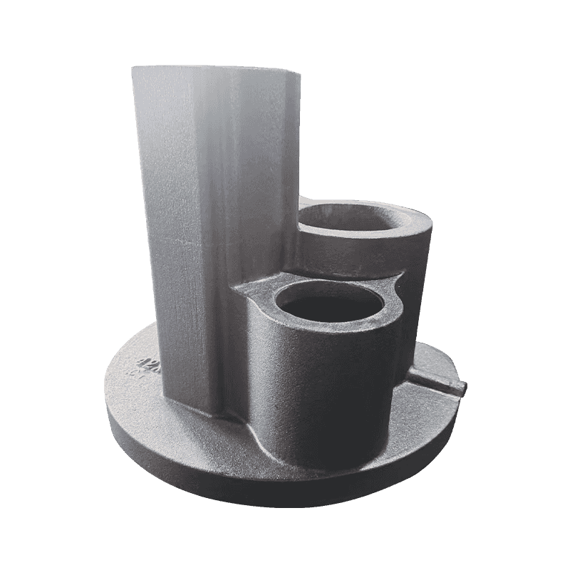
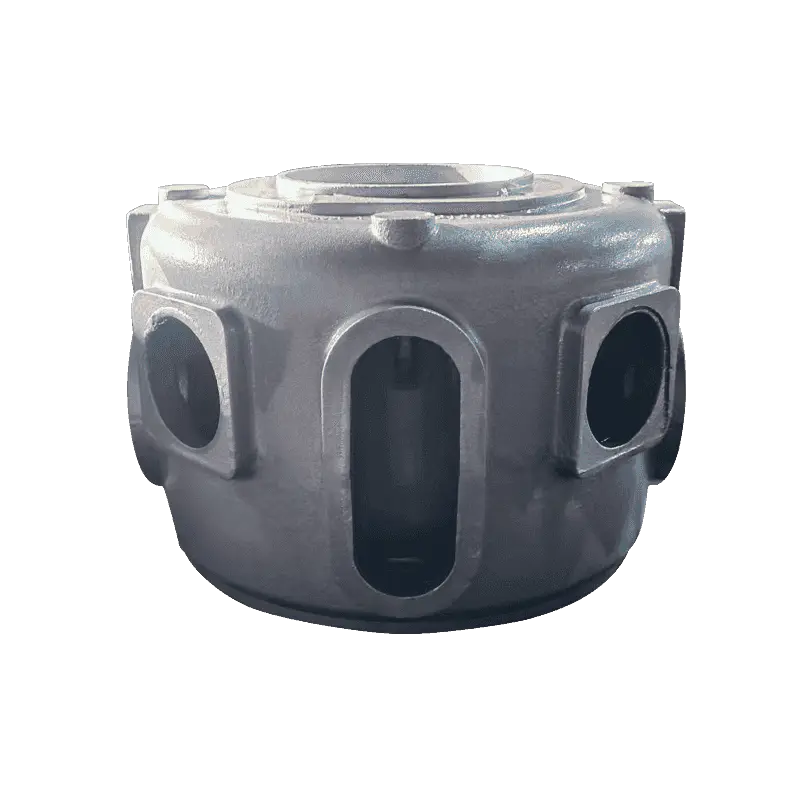
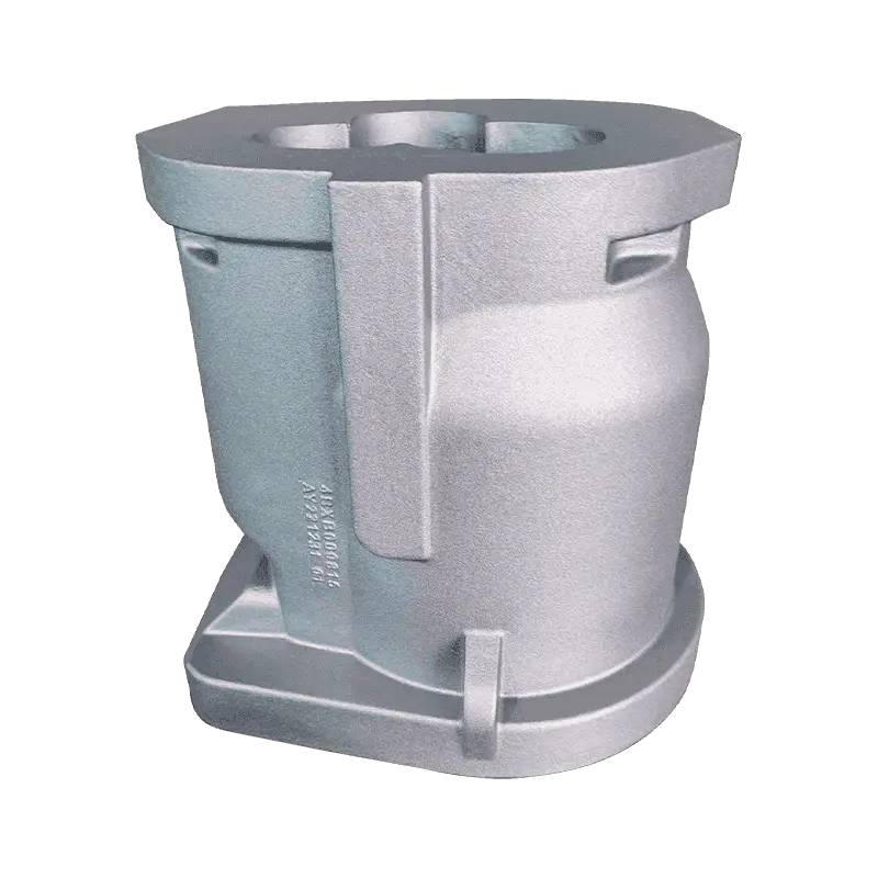
Most rejections on machined ductile iron castings are geometric, not cosmetic. A compressor body ties together a mounting face, a main bore and several shaft seats. Indicate that bore from a raw casting face and the tolerance you are really working to is the pattern's, not the machine's.
The sequence that holds up is unglamorous: rough the datum faces, let the casting settle, then finish the bore and machine every related seat from it. Ductile iron's higher strength lets designers thin the walls compared with gray iron, which helps weight and hurts stability, because a thin housing deflects under clamping and relaxes after the cut.
Machining allowance is the other half of that conversation. Too little allowance forces a shallow rubbing pass; too much means an extra roughing operation and a higher chance of opening porosity.
| Casting size (max dimension) | Single-face allowance | Typical parts |
|---|---|---|
| Up to 150 mm | 2-3 mm | Covers, small housings, machined pads |
| 150-500 mm | 3-5 mm | Pump bodies, bearing housings, valve bodies |
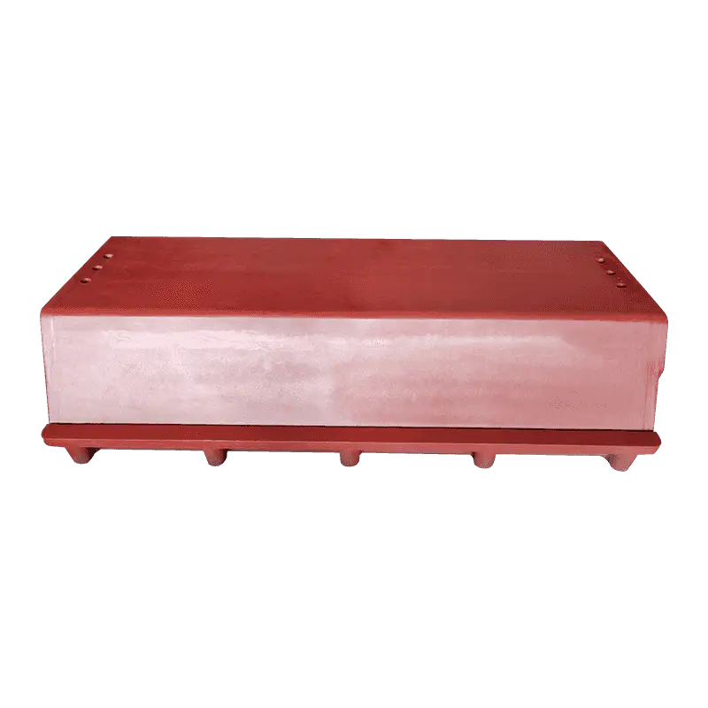
| 500-1500 mm | 5-8 mm | Compressor bodies, machine bases |
| Over 1500 mm | 8-12 mm | Columns and large frames |
Frames and Columns: Where Vibration Sets the Finish
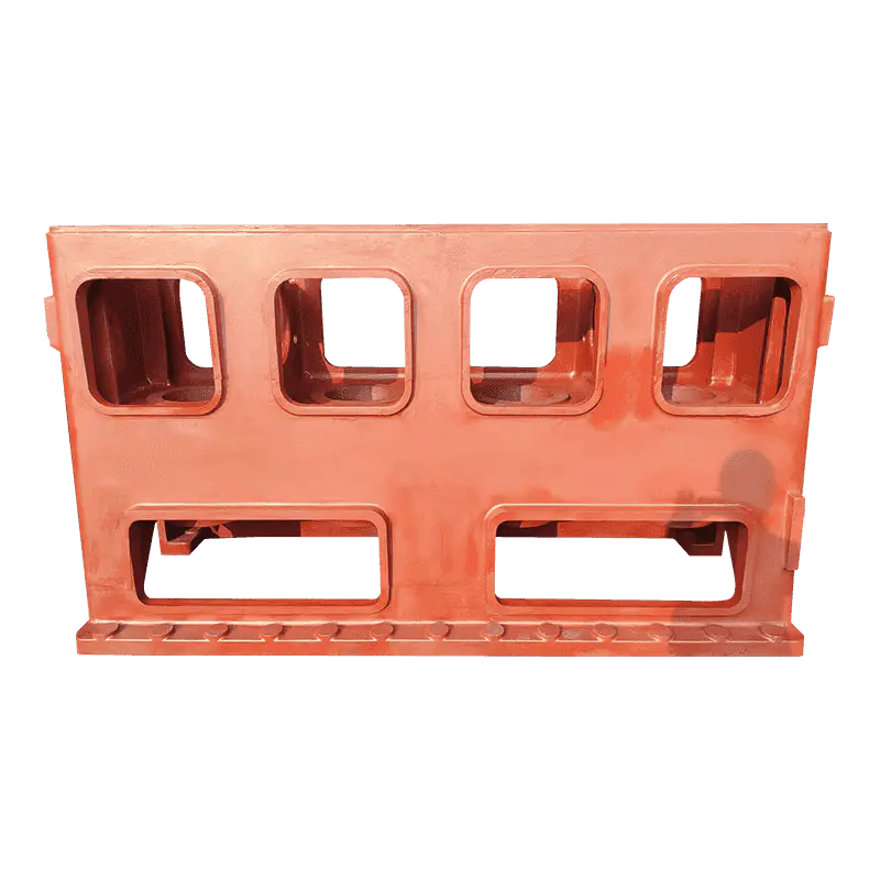
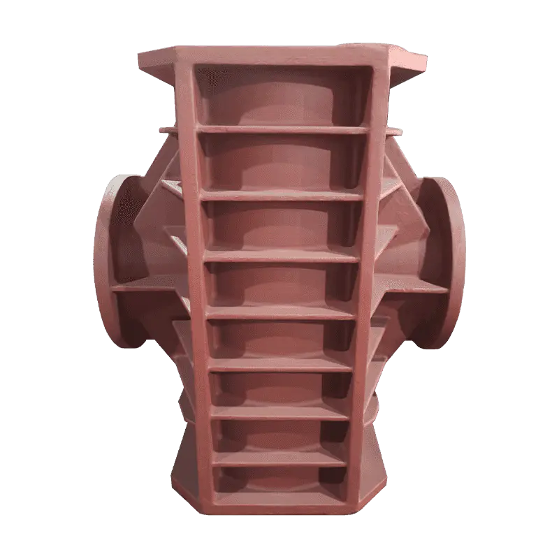
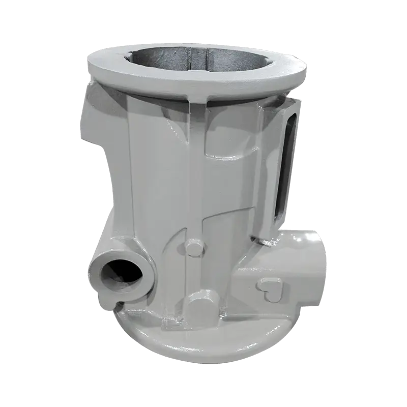
Machine tool builders choose between gray and ductile iron for reasons that show up in the cut. Flake graphite in gray iron converts vibration into heat effectively, so beds and slides that must stay quiet are often gray iron. Nodular graphite gives up some of that damping but brings higher strength and stiffness, which is why columns and structures under bending load are frequently ductile iron.
For the machinist, that means a large casting has to be stable before it can be accurate. Thermal equilibrium with the shop matters as much as clamping: a column rough-machined cold and finished warm will move between operations. The wider picture of how casting quality carries into machining accuracy is worth reading before the drawing is frozen.
In practice: machine the mounting face first, indicate the rail seats from it, and hold the finishing pass until the part has stopped moving. On tight tolerances, measure on two different days.
Pump and Valve Bodies: Wall Thickness and Leak Paths
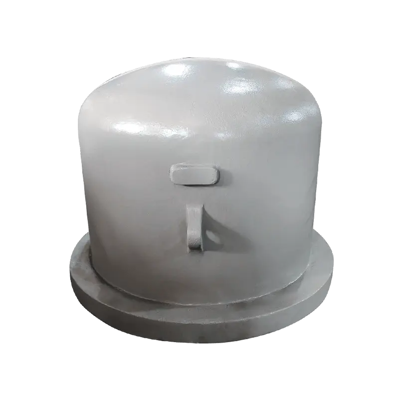
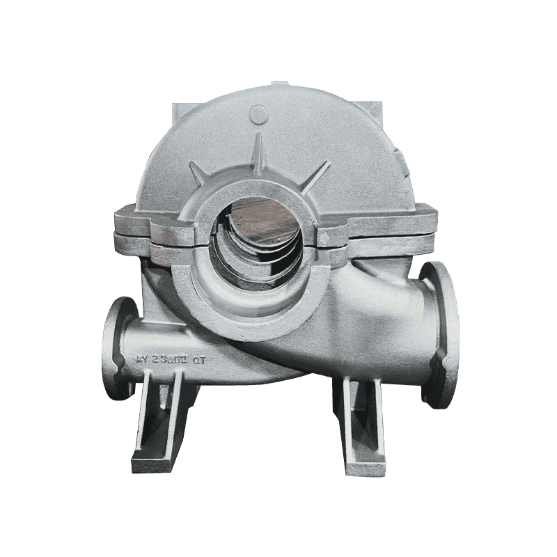
Pump casings and valve bodies are pressure boundaries, so a hidden defect carries a heavy price. A pore buried in a wall is a casting; the same pore opened by a boring bar is a scrapped part with machining hours already invested in it.
Two habits reduce that risk. Specify non-destructive examination on pressure boundaries before machining rather than after, because radiography or ultrasonic testing on a rough casting costs far less than a finished part with a weeping seal face. And put flatness and parallelism on the drawing for flange faces and seal bores, since general dimension tolerances rarely control the feature that actually leaks.
Ductile iron earns its place here by tolerating water hammer, thermal cycling and pressure spikes that would crack a more brittle material. The machining consequence is simple: seal faces and bolt circles have to hold their geometry after hydro-testing, not only on the bench.
What to Settle Before the First Cut
Reliable machining of ductile iron castings is mostly a purchasing habit rather than a tooling secret. Put these points on the order and the shop floor stops guessing:
- A grade plus a hardness range, with the test location stated.
- Machining allowance by feature, not one blanket figure.
- Datum definition, and whether the datum is as-cast or machined.
- Acceptance criteria for porosity on pressure and sealing surfaces.
- Sample approval that includes a hardness map from a sectioned part.
The payoff: when hardness spread is controlled and datums are agreed, ductile iron machines at predictable speeds with predictable tool life. The variable that remains is the one you chose to leave open.
Haian Aoyu Machinery Manufacturing produces ductile and gray iron castings for compressor, pump, valve and machine tool builders, with roughly 20,000 tons of annual casting capacity and export experience across Europe, Japan and North America; you can review the full casting scope behind these parts before you place a drawing on a supplier's desk.