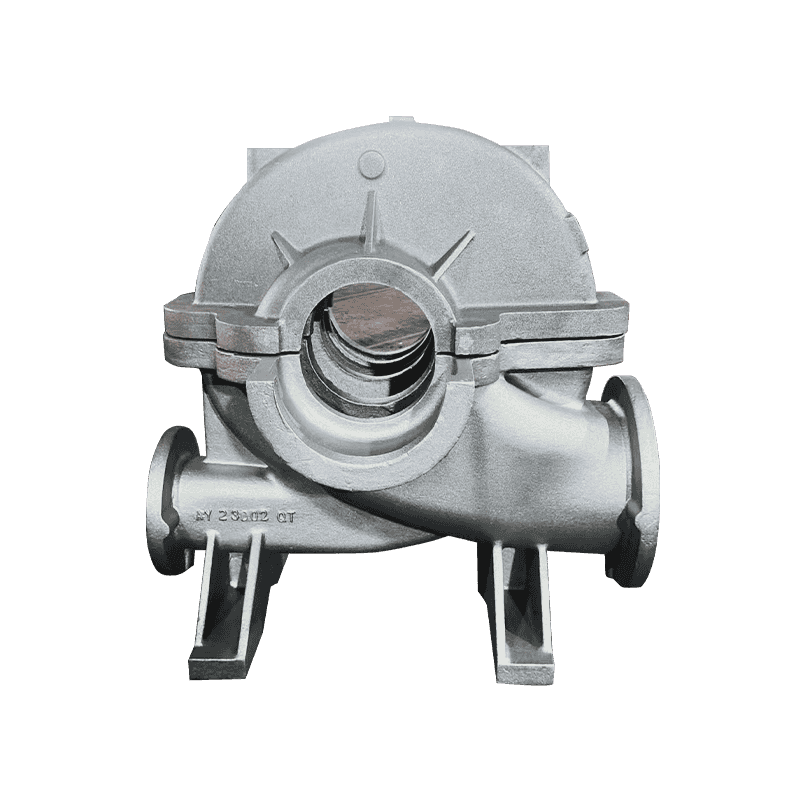
Axial flow pumps function based on the principle of imparting momentum to the fluid primarily in the axial direction using propeller-type impellers. Unlike centrifugal pumps, which generate head through centrifugal force, axial flow pumps generate head by lifting fluid along the shaft axis. Because of this, the developed head is relatively low, and even minor increases in discharge pressure (backpressure) significantly impact the flow rate. A sudden increase in downstream resistance—such as a partially closing valve or accumulation of debris—can result in a marked drop in throughput. This makes axial flow pumps less forgiving in systems where backpressure can change rapidly.
The pressure-flow characteristic (also known as the pump curve) of an axial flow pump is nearly horizontal over a wide range of flow rates. While this allows the pump to operate across varying flow demands without drastic pressure change under stable conditions, it presents challenges when conditions fluctuate unpredictably. In response to sudden demand drops or surges, the flatness of the curve provides minimal head adjustment range, potentially leading to flow oscillation, instability, or operation at off-design points where efficiency and reliability degrade. This behavior contrasts sharply with radial or mixed-flow pumps, whose steeper curves inherently buffer system transients.
Rapid backpressure changes can lead to transient phenomena such as hydraulic surges, especially in long pipeline systems where water hammer effects can propagate. Axial flow pumps are especially vulnerable to these events due to their large impeller blades and open-flow design. If flow is suddenly restricted or reversed, impeller blades may experience flow separation or stalling, producing severe turbulence and asymmetric loading. In extreme cases, when discharge pressure exceeds inlet pressure, flow reversal may occur, spinning the impeller backward and damaging shaft seals, bearings, or motor components. To prevent these effects, surge arresters, expansion chambers, or anti-reverse check valves must be properly engineered into the system.
The axial flow pump’s impeller is designed to operate under balanced flow conditions. However, when rapid changes in system pressure or flow rate occur, the torque required by the motor changes almost instantaneously. This imposes fluctuating electrical loads on the motor and can result in overheating, reduced power factor, and electrical instability if not properly mitigated. Mechanical load variation also manifests as axial thrust fluctuations on the shaft, which stresses bearings and mechanical seals. In vertical configurations, where the pump shaft is long and may include line bearings, sudden axial loading shifts can cause shaft deflection or misalignment.
To ensure reliable operation during system transients, axial flow pumps are frequently coupled with automated control architectures. These include variable frequency drives (VFDs) that regulate motor speed based on real-time system feedback, thus allowing gradual adjustment of flow output in response to changing demand. In more complex systems, PLCs (Programmable Logic Controllers) and SCADA systems integrate with pressure transducers, flowmeters, and temperature sensors to provide closed-loop control. These controls prevent pump overloading, minimize energy use, and stabilize discharge characteristics. The addition of PID controllers further enhances smooth transitions during ramp-up, shut-down, or load-switching events.

